STOP PRESS – NO MORE 3D PRINTING
3D Systems have removed the Projet 4500 3D printer from the market and no longer support 3D printing with this machine. Thus all the coloured 3D printed models advertised for sale on this webpage are no longer available. You are welcome to view the images and videos and we will maintain the website for some time to come. If there is a demand we can 3D print the models with cheaper, monochrome plastic that can be hand painted – prices on application.
In the meantime we have developed polyurethane replicas of archived horse foot material. Currently priced at AU$80.00 each, plus shipping costs, these economically priced models are ideal for student teaching and client education.
[ngg_images source=”galleries” container_ids=”8″ exclusions=”121″ display_type=”photocrati-nextgen_pro_thumbnail_grid” override_thumbnail_settings=”0″ thumbnail_width=”250″ thumbnail_height=”250″ thumbnail_crop=”0″ images_per_page=”4″ border_size=”0″ border_color=”#eeeeee” spacing=”2″ number_of_columns=”0″ ngg_triggers_display=”always” ngg_proofing_display=”0″ captions_enabled=”1″ captions_display_sharing=”1″ captions_display_title=”1″ captions_display_description=”1″ captions_animation=”slideup” order_by=”sortorder” order_direction=”ASC” returns=”included” maximum_entity_count=”500″]
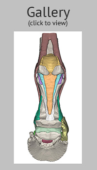
View the New Models

Professor Christopher C. Pollitt and Dr Simon N. Collins at 3D VetAnatomize in Australia announce 3D printing of the horse’s foot in a new, improved coloured plastic medium. In the future all 3D VetAnatomize models will be printed using the Projet 4500 3D printer from 3D Systems. The resultant models are still life size and coloured but now more durable and less fragile.
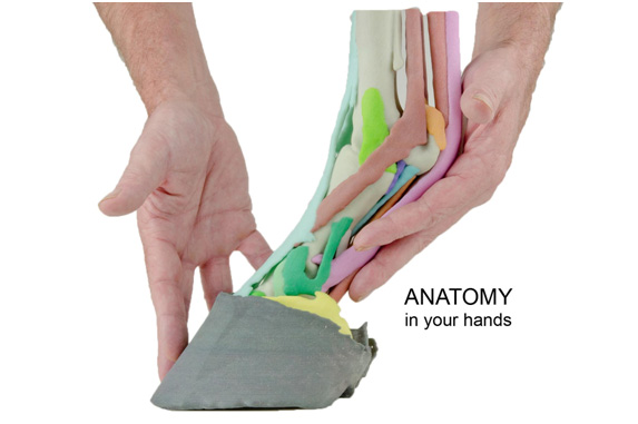
Hold the foot of a living horse in your hands and you wonder about the structures inside. Not completely understanding it, you try to explain the anatomy of the bones, ligaments, tendons and joints to your clients, students and colleagues. Superimpose disease or injury and the task becomes even more difficult. Only a few experts comprehend the horse’s foot in three dimensions and even they struggle to explain it to others. What is needed is anatomy in 3 dimensions, comprehensible to all and preferably, something to hold in your hand.
Anatomical aids are available in the form of two dimensional diagrams, freeze-dried and plastinated sagittal sections and fibre glass models based on dissected specimens and artistic interpretation. More recently access to virtual models that can be manipulated in three dimensions and dissected via the computer monitor are a welcome advance. While these modalities are useful and are steadily improving in quality and accuracy a breakthrough has come with 3D printing. Now an anatomically correct, life-size model can be held in the hand and viewed from all aspects (Fig 01).
Additive manufacturing, more commonly known today as 3D printing is fast becoming a widespread and accessible modelling technology. Aircraft and car parts, fashion accessories and even prosthetic medical implants can be rapidly custom manufactured in various materials. However to be able to print in the third dimension data in three dimensions are required. In the case of anatomy this is derived from images made by advanced imaging techniques such as magnetic resonance (MR) and/or computed tomography (CT).
The office inkjet printer can spray patterns onto paper in two (X & Y) dimensions and we are all familiar with this – the pages you are reading may have been printed in this way. Now imagine if the printer continued to print the same pattern over and over, adding to it in the vertical or Z direction – with binder linking together the individual layers. The layers will increase in height until the entire model is built, one layer at a time. This ‘additive manufacturing’ or 3D printing builds components layer by layer so that virtually nothing is wasted.
Anatomical specimens imaged by either computed tomography (CT) or magnetic resonance (MR) produce quite different results. CT gives excellent bone resolution while MR is superior for soft tissue visualization (Fig 02).
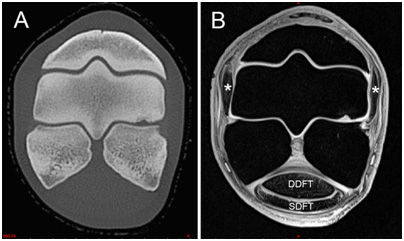
Each of these advanced imaging techniques produces a vertical image stack (z-stack) of individual 2D images (each image separated by fractions of a mm) resolved in various shades of grey (grayscale) which is applied to each of the pixels making up the 2D image. Anatomical structures are identified by their grayscale appearance, shape and relationship to other structures. In medical or veterinary practice the clinician scrolls through the individual images of the z-stack on a computer or if they are printed on film compares images one to another and makes a diagnosis based on experience and expertise. However, the image stacks can be handled in a different way.
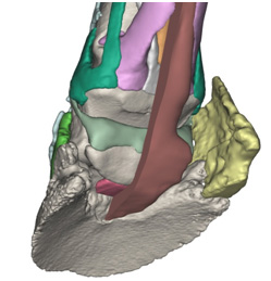
With appropriate computer software the stacked 2D image data can be combined to produce a 3D image composed not of pixels but voxels – a pixel in 3D. By painstaking analysis and hours of computer time each tissue can be discriminated and segmented as a virtual entity until anatomical structures (such as ligaments, tendons or bones) are built on the computer monitor. The software allows enlargement and rotation of the model and switching on and off of various components to virtually dissect it (Fig 03). The leap forward in anatomical comprehension and understanding has to be experienced to be believed.
Professor Christopher C. Pollitt and Dr Simon N. Collins at 3D Vet Anatomize in Australia took a normal Standardbred stallion distal limb (ethically euthanased on welfare grounds) and placed it in a wooden, non-magnetic positioning jig to replicate weightbearing at stance. Thus locked in place the limb was scanned in a high resolution (3T) MR scanner for soft tissue imaging. Still in its positioning jig the limb was also CT scanned to obtain high resolution bone Images. Using Materialise MIS software both sets of image data were co-registered to produce an accurate anatomical model of the weightbearing horse foot. Colours were ascribed to each of the 26 individual structures, for anatomical cross-referencing in various views.
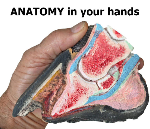
Using ‘state of the art’ 3D printing software the individual anatomical structures were hollowed, and fused together ready for printing. The model prototype was printed using a multicolour powder printer from ZCorp. The Z printer bonds a white composite gypsum powder and adds colour following the colour coding ascribed to the virtual model. The first models to emerge from the Z-printer were like beautiful works of art; exquisitely accurate and coloured in pastel shades with a ceramic-like quality (Fig 1). Unfortunately the ceramic resemblance of the prototype was all too accurate and they fractured easily with general handling in the anatomy laboratory or farrier’s workshop.
Urgently needed was a 3D printer that could offer multicolour printing in a more durable plastic based material. Just such a printer has arrived on the market; the ProJet 4500 described by its manufacturer 3DSystems as “the industry’s only continuous tone full-color plastic 3D printer.” Printed on the ProJet 4500 the 3DVetAnatomize foot models look just the same, their anatomical accuracy is maintained but now they have durability needed to meet the handling demands of such a model for teaching and demonstration purposes. All future foot models will be printed this way.
The printed models currently available range from full anatomy (composed of all 26 coloured components) to progressively reduced models showing deeper structures. The hoof capsule is separate and anchors the distal limb in the weightbearing stance position (Fig 04).
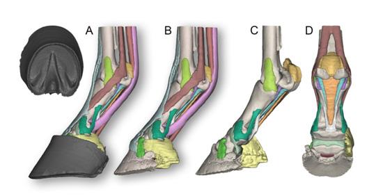
The complete model (Model 002) shows the following colour coded structures (Fig 04): Third metacarpal bone; Proximal sesamoid bones; Proximal phalanx; Middle phalanx; Distal phalanx; Distal sesamoid (navicular) bone ; Ungular cartilages; Collateral ligaments of the metacarpophalangeal joint; Collateral ligaments of the proximal interphalangeal joint and the abaxial palmar ligaments of the foot; Collateral ligaments of the distal interphalangeal joint; Collateral ligament of the distal sesamoid (navicular) bone; Distal sesamoidean impar ligament; Proximal scutum and intersesamoidean ligament; Cruciate sesamoidean ligament; Short sesamoidean ligaments; Oblique sesamoidean ligaments; Straight sesamoidean ligament; Axial palmar ligaments of the foot; Suspensory ligament and extensor branches; Deep digital flexor tendon; Superficial digital flexor tendon; Common digital extensor tendon; Hoof capsule.
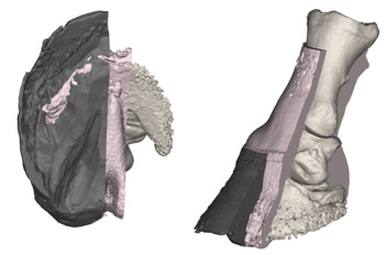
Perhaps the most popular is Model 004. It is similar to the Model 002 master but with the deep flexor tendon split sagittally to show its relationship to the distal sesamoid (navicular) and the distal sesamoidean impar ligament (Fig 05). One ungular cartilage is removed to show the collateral ligaments of the distal sesamoid. This model is ideal to explain the biomechanical relationship between the deep digital flexor tendon and the flexor surface of the distal sesamoid bone and their links to ‘palmar foot pain’ and ‘navicular syndrome’.
Also available is The White Model (Model 06) 3D printed in white plastic ready for hand painting with your own acrylic hobby paints. Painting this model, following the supplied colour code, makes an interesting ‘test your knowledge’ anatomy quiz.
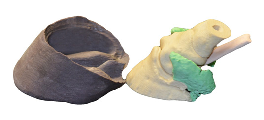
The model of an Outback Brumby Foot (Model 001) was the first to be printed. It is a two part model with the hoof capsule separate (Fig 06). The distal phalanx, middle phalanx, distal sesamoid, the distal half of the proximal phalanx, both ungual cartlilages and deep flexor tendon attach to each other as a single unit. The hoof displays the natural, bevelled trim acquired by interaction with the hard stony terrain of its environment.
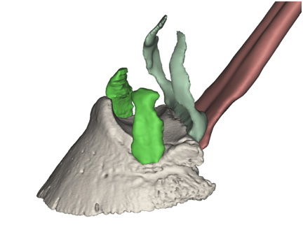
Recently added to the collection is the foot of a severe case of chronic laminitis (Model 007). Derived from high resolution CT data the model illustrates the destructive effect of severe chronic laminitis (Fig 08). The hoof capsule and a section of the adjacent soft tissues is cut along the midline. There is extensive modelling of the distal phalanx including lysis of the distal margin, enlargement of vascular foramina and reactive new bone formation. The distal phalanx has sunk within the hoof capsule resulting in a classic dropped sole with stretching and distortion of the coronary, lamellar and solear dermis. The solear dermis projects through gaps within the sole where the distal phalanx has caused pressure necrosis. A separate model of the entire hoof capsule is included. The hoof capsule shows abnormal growth patterns, capsular distortion, lamellar wedge formation and focal necrosis of the sole.
The range of available models can be viewed and ordered on this website.
Orders will be printed by a specialist 3D printing bureau that will handle printing, billing and dispatch. The 3D printing bureau will be in the region of the order to ensure speedy delivery. 3DVetAnatomize will consider creating bespoke models from CT or MR data from outside sources. Submit data in a zipped folder to the website email address 3dvetanatomize@gmail.com for analysis and quotation.
In conclusion, through the magic of additive manufacturing (3D printing), you can now hold a life-size horse’s foot in your own hands. Not a preserved dissection but a dry, clean, anatomically correct model derived from CT and MR data. Anatomy models with a difference – IN YOUR HANDS.